
Open Systems Interconnection (OSI) Model
- emsuraki5
- Aug 26, 2025
- 4 min read
In this blog, we are going to take a look at an essential model used in networking which is the Open Systems Interconnection Model (OSI model). The OSI model provides a framework that dictates how all network devices will send, receive and interpret data. OSI model consists of seven layers which we are going to dive into in this post. Each layer has a different set of responsibilities and is arranged from Layer 7 to Layer 1. As data travels through each layer, specific processes take place, and pieces of information are added to this data. A mnemonic to remember the different layers is Please Do Not Throw Sausage Pizza Away
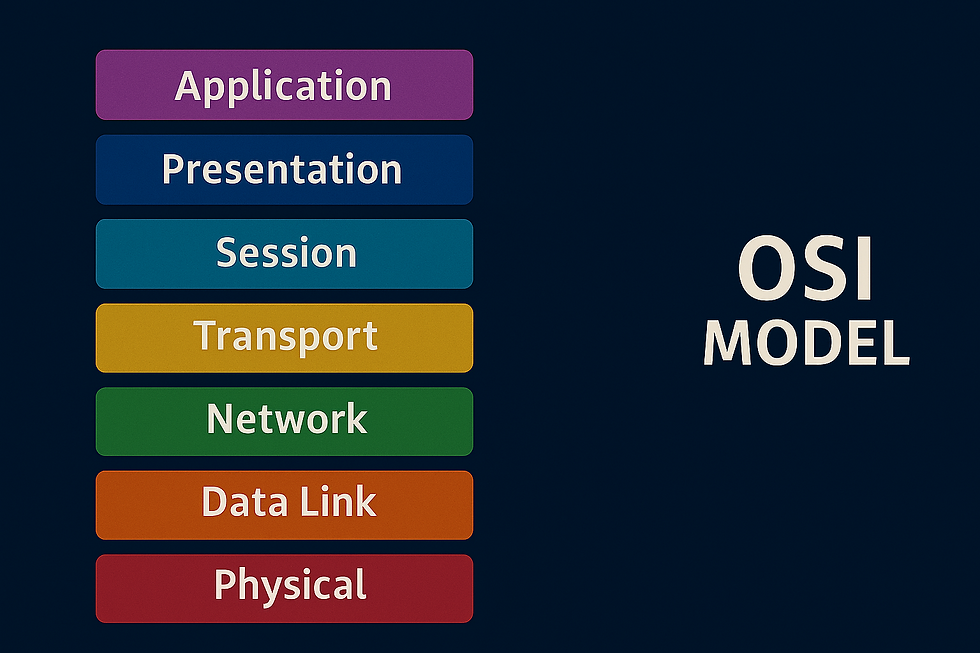
Layer 1 - Physical
This layer references the physical components of the hardware used in networking and is the lowest layer in the OSI model. Devices uses electrical signals to transfer data between each other in a binary numbering system (1s and 0s) e.g ethernet cables

Layer 2 - Data Link
Data link layer focuses on the physical addressing of transmissions. It:
Receives a packet from the network layer (including IP address of remote computer)
Adds in the physical MAC (Media Access Control) address to the receiving endpoint.
Presents the data in a suitable format for transmission.
Important to note that inside every network-enabled computer is a Network Interface Card (NIC) which comes with a unique MAC address to identify it. These are set by the manufacturer and can't be changed - although they can be spoofed.
Layer 3 - Network
This is where the magic of routing and re-assembly of data takes place i.e from small chunks to the larger ones. At this layer, everything is dealt with IP addresses like 192.168.1.100. Layer 3 devices like routers are capable of delivering packets using IP addresses.
Routing in layer 3 determines the most optimal path in which the chunks of data should be sent. There are protocols like Open Shortest Path First (OSPF) and Routing Information Protocol (RIP) that determines exactly which optimal path that data should take to reach a device. Factors that determines which route to take is decided by:
What path is the shortest? i.e has the least amount of devices that the packet needs to travel across
What path is the most reliable?
Which path has the faster physical connection? i.e is one path using copper (slower) or fibre (faster)

Layer 4 - Transport
Layer 4 is where the transmission of data across a network happens and follows one of two different protocols - TCP or UDP
Transmission Control Protocol (TCP)
TCP is designed with reliability and guarantee in mind. It reserves a constant connection between the two devices for the amount of time it takes for the data to be sent and received. TCP also implements error checking which guarantees that data sent from small chunks in Layer 5 has been received and reassembled in the same order. TCP is used for file sharing, internet browsing, or sending email which requires data to be accurate and complete.
User Datagram Protocol (UDP)
UDP is not build to reliability like TCP or error checking. Even though it is faster than TCP, it does not guarantee delivery of the data. There is no synchronisation between the two devices. UDP is useful where there are small pieces of data being sent. e.g protocols for discovering devices (ARP & DHCP)
Layer 5 - Session
The session layer creates and maintains connection to the destined device for which the data is to be sent. This is one data has been correctly formatted from the presentation layer. Once a connection is established, a session is created. As long as this connection is active, so is the session. Also responsible for closing the connection if it is lost or hasn't been used for a while. To save on bandwidth, the session layer can contain checkpoints, where if there is data lost, only the newest pieces of data are required to be sent. Sessions are unique meaning data cannot travel over different sessions.
Layer 6 - Presentation
Standardisation of data takes place in this layer. Data needs to be handled the same no matter how the software works. Presentation layer acts as a translator for data to and from the application layer. It ensures data looks the same across different systems. For example, even if two people use different email apps, the message still appears correctly—thanks to the presentation layer handling format and translation. Security features like data encryption (HTTPS) occur at this layer
Layer 7 - Application
This is where protocols and rules are in place to determine how a user interacts with data sent or received. Everyday applications like web browsers, or email clients provide a friendly Graphical User Interface (GUI) for users to interact with data sent or received. There are other protocols like Domain Name System (DNS) which translates website addresses into IP addresses which computers are familiar with.
Conclusion
The OSI model breaks down how data travels across networks into 7 layers—from physical wires to user-facing apps. Each layer has a job: moving bits, routing packets, translating formats, and keeping communication secure and seamless. Think of it like a well-organized village: every role matters, and harmony ensures the message gets through.
As a look forward, stay tuned to more topics as we dive deeper into the Networking world. Let me know in the comments your feedback and if there are any other topics you would like to see covered.

Comments